| Search | Contact Us _ | Classifieds _ |


![]()
![]()
|
|
|
|
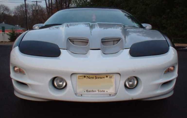
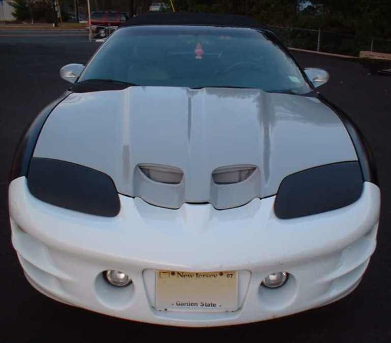
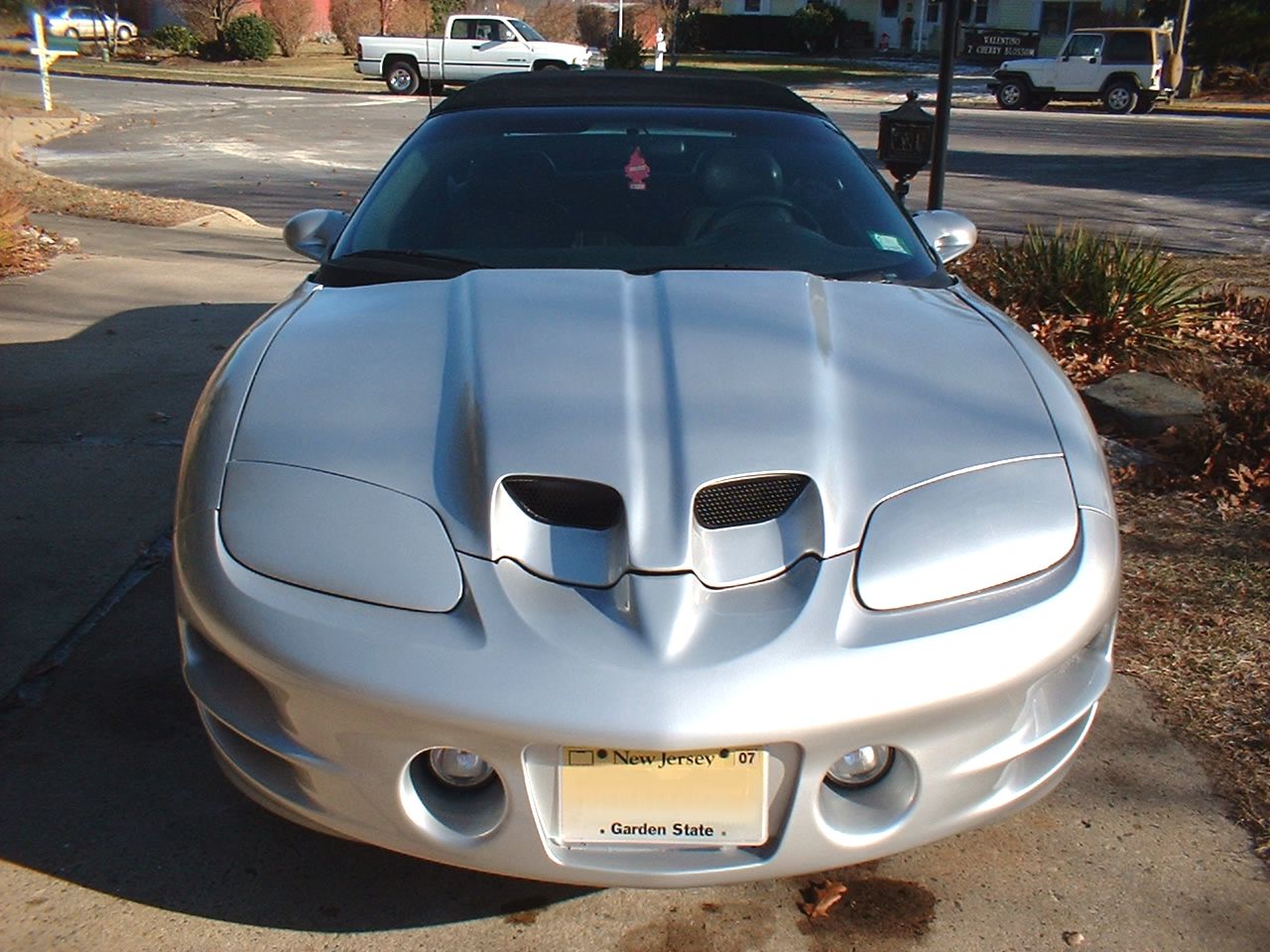
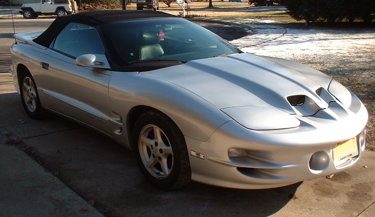
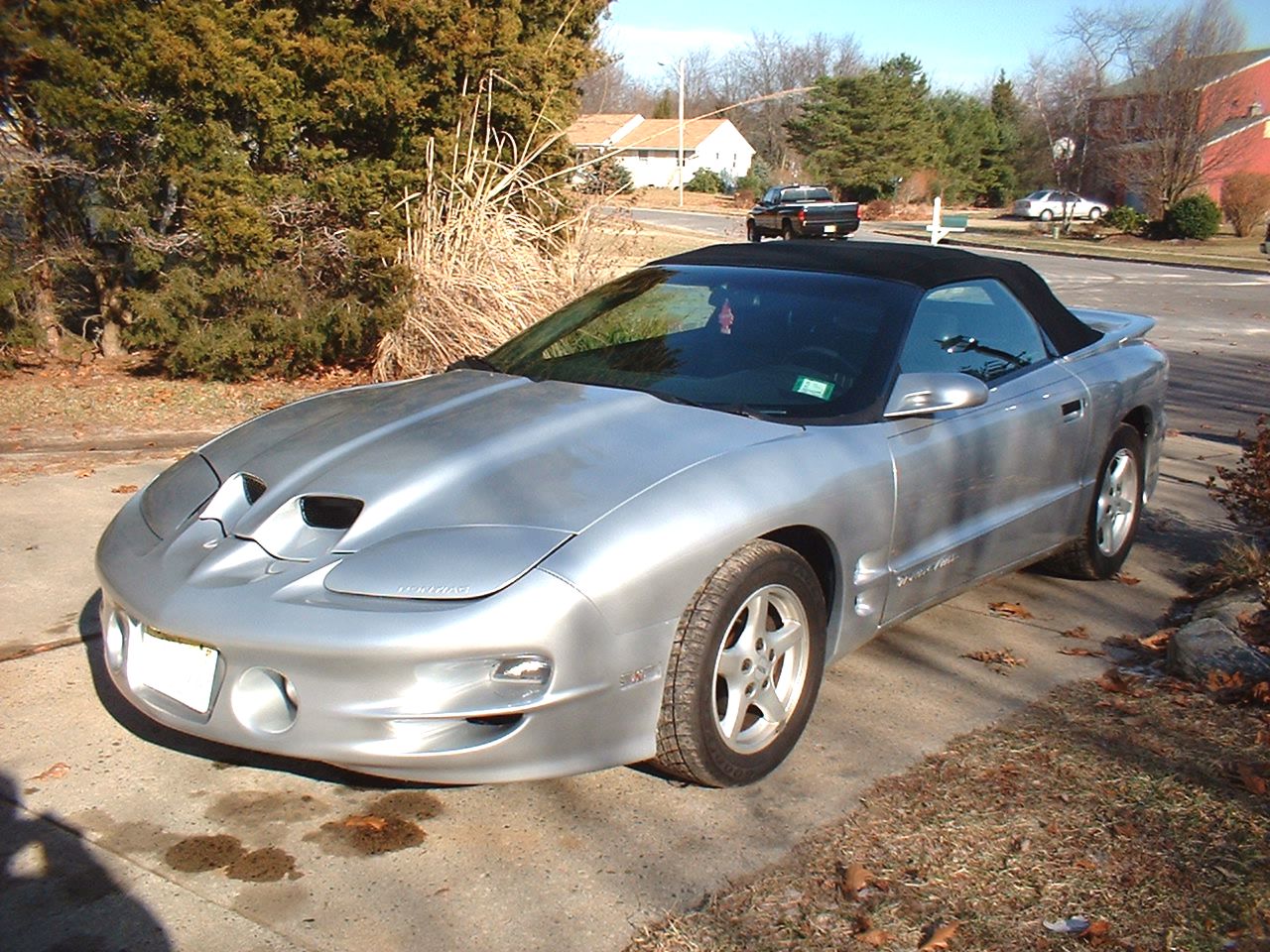
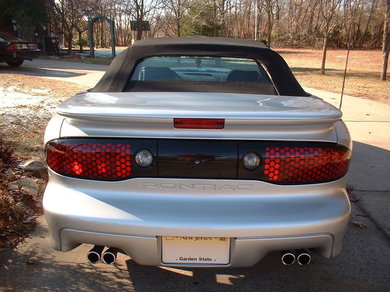
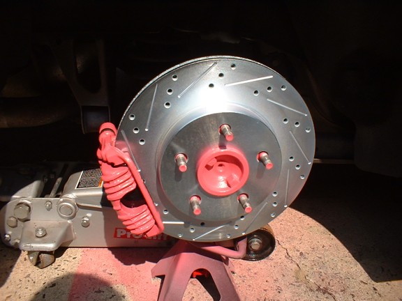
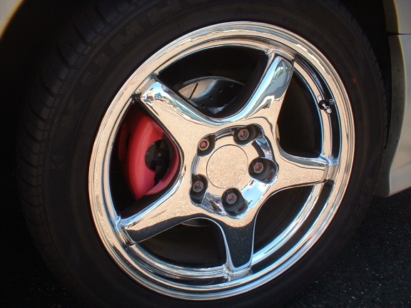
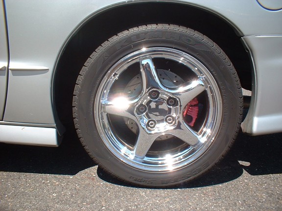
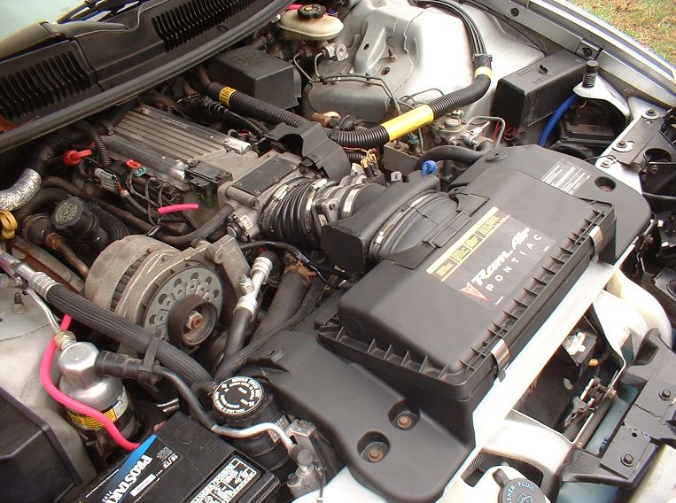
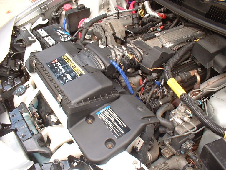
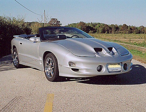
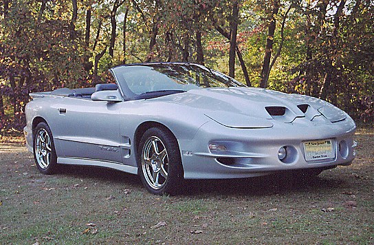
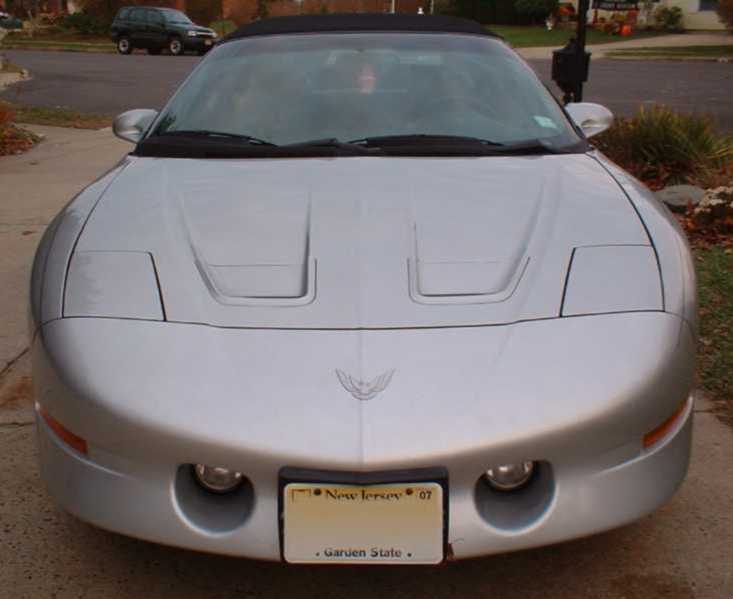
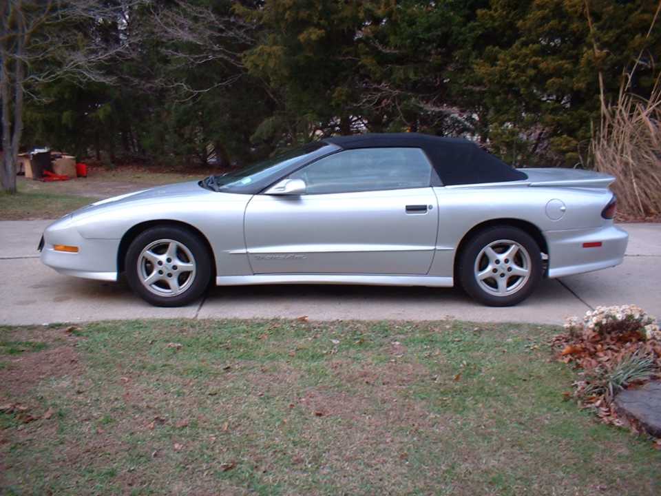
9-17-04 UPDATE: Drilled & slotted brake rotors In an effort to improve the braking performance of our 1995 Trans Am, and also because the old brake rotors and calipers stick out like a sore thumb with the chrome ZR1 rims, we decided to replace the stock brake rotors with a full set of zinc coated CNC machined cross drilled and slotted brake rotors. While we were at it, we painted the calipers and brake hardware. Now I know that some of you may be questioning the color, but this vehicle is my fiancés, so it's her call when it comes to color choice. With that said, here is the install. We first started by removing the calipers and then the old stock brake rotors. Then we cleaned the surfaces to be painted with brake cleaner and then lacquer thinner. We followed that up by wiring brushing and sanding every surface that was going to be painted. Then we whet over everything with lacquer thinner again to insure that we removed anything that would inhibit the adhering of the primer and base coat. This step of cleaning and re-cleaning the surfaces to remove all the dirt, grease, and brake fluid is crucial. Not completing that step is usually the reason why so many brake painting projects go bad. Once all surfaces were fully prepped, and everything that wasn't supposed to be pink was taped off, we applied two primer layers of flat white. Once the primer had dried, we sanded them with 220 grit sand paper. Then we began to apply the four base coats of pink. We used four coat to ensure full coverage. Once the base coats had dried we then applied three coats of clear. We allowed the paint to fully cure for a full day before reassembling the brakes. The rotors that we acquired are direct replacements for the stock rotors, and require no modifications to the stock brake set up. They installed just as easily as a set of stock rotors. The only difference was the strict break in procedure required to remove the zinc coating from the braking surface. We finished up the install with a brand new set of performance brake pads. Now the Trans Am's braking performance is a night and day difference. We currently have one full set of these same rotors for sale on our website. Act fast and get them for an incredible price!!! click for more details, and visit our Performance Products Page to purchase. 11-21-03 UPDATE: Project Rare Bird featured in calendar Our Project Rare Bird is featured in SLP's 2004 Calendar!!! The calendar can be purchased on SLP's website. Hopefully next year Project Rare Bird will be featured on the cover 10-23-03 UPDATE: Cosmetic & Performance Enhancements We have made a few cosmetic as well as performance improvements on our project Rare Bird since we finished the body and paint work. We started by removing the charcoal pin striping that was on the car when we purchased it. We also upgraded the rims to Chrome SLP ZR1 17x9.5in and Kumo 275-40-ZR17 tires. We also installed one of our LED Sequencers and mounted quite a few of our 12volt LED's throughout the interior. On the performance end, the engine of our Project Rare Bird has not been modified except that we added a stock air box and lid from an LS1 equipped WS6 Ram Air Trans Am to the 1995 LT1. The install was a bit tricky and did require us to modify the bottom of the air box so it would mount on the LT1's radiator support. Once we got the air box to sit in it's desired location, it was just a matter of using the stock outer two mounting points and then drilling and taping holes for the inner two mounting bolts. Once the air box was mounted, we then tried to figure out how to get the stock LS1 air box to mate with the LT1 throttle body. We accomplished this by cutting the stock LT1 rubber elbow just before the bend. Then we cleaned it up to fit perfectly on the ovular LT1 throttle body and attached the other end to the LT1's mass air flow sensor. We were then faced with another dilemma. Using the stock air silencer would allow us to mate the air lid to the mass air flow sensor, however when we installed it we found that the air silencer hit the alternator pulley. This forced us to fabricate a custom piece that would accept a ovular port on one end to mate to the air lid, as well as a round end on the other side to mate to the mass air flow sensor. We would also need provisions for the air intake temperature sensor, and the air tube for the opti-spark. We finally decided that the easiest solution was to modify the stock LS1 air silencer. This would cut out some of the fabrication work as the air intake temperature sensor was already mounted in it. We just cut off the two ends of the silencer; then using a homemade plastic welder (hot air torch, and a Exacto knife) welded the two open ends. Then we drilled a hole for the opti-spark's air tube (view third picture below). We also had to lengthen the air intake temperature sensor harness so that it could reach the new location of the air temperature sensor. We also needed to lengthen the mass air flow sensor harness but luckily all we had to do was cut loose some of the wires from the wire bundle which gave us the extra length we needed. We finished the install with a new K&N air filter to have completely functional ram air system. The install looks almost stock and you can really feel the difference in performance with the SLP Raptor Ram Air hood now functional. Pictures of our completed 'Project Rare Bird' 1995 Pontiac Trans Am. 1-25-03: Full Article on Project Rare Bird Conversion Recently there has been an increasing number of F-Body owners who decide to take the leap and convert their 93-97 front end into the more desirable 98-02...and I can now add my name to that list. In my research prior to the start of this project, I found that there was a sparse amount of information on the web regarding such an undertaking. Now that I have completed the project with success, I decided to create the type of page I would like to have seen before I began. Hopefully this page will assist some fellow F-Body fans in their quest to convert. Please note that one of the goals of this project was to do the conversion for the least amount of money possible. The base vehicle that we used was a 1995 Pontiac Trans Am Convertible. Preliminary Phase: Acquiring the necessary parts When purchasing parts for your project, it can become frustrating as your bill goes up and up in price... But remember, once you have completed your conversion, you can easily sell your old parts and make a good portion of your money back. Here is a list of parts and prices I used for the conversion of my 1995 Pontiac Trans Am Convertible:
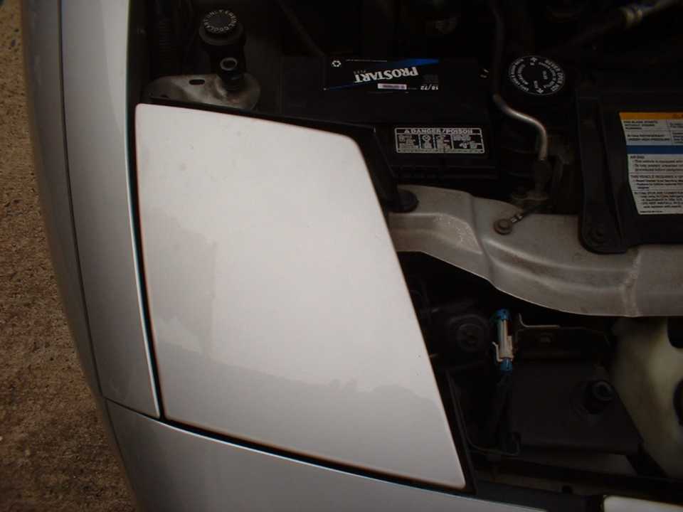
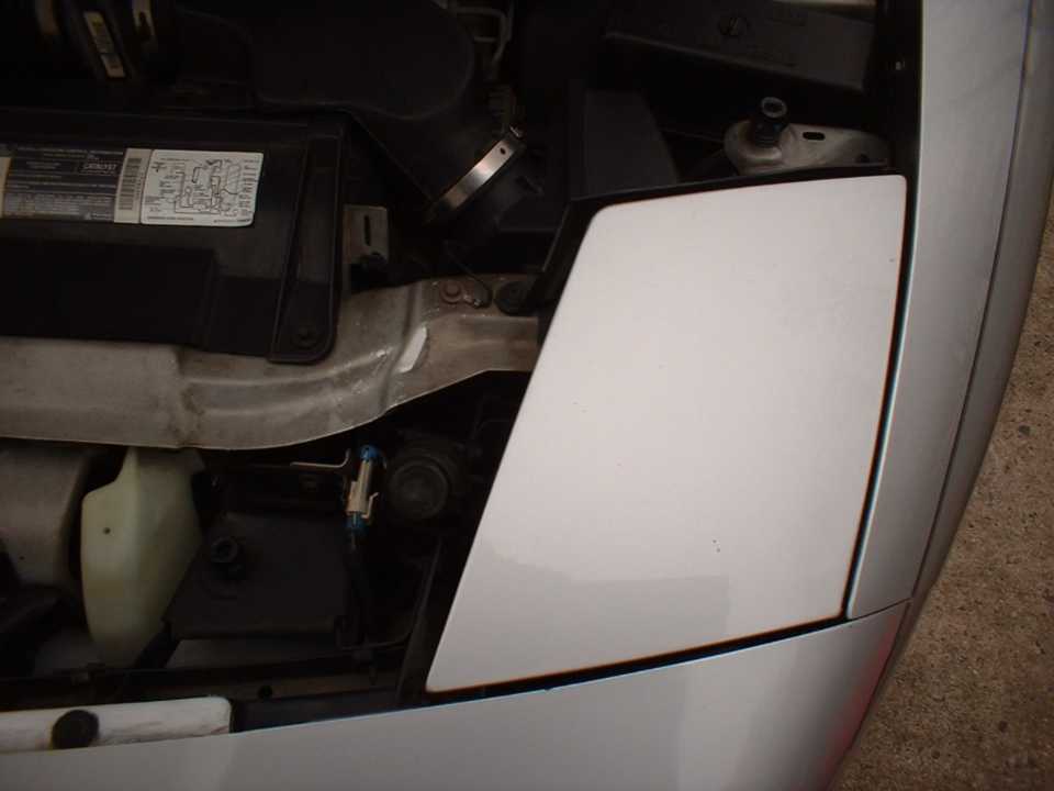
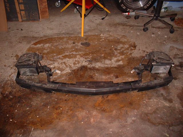
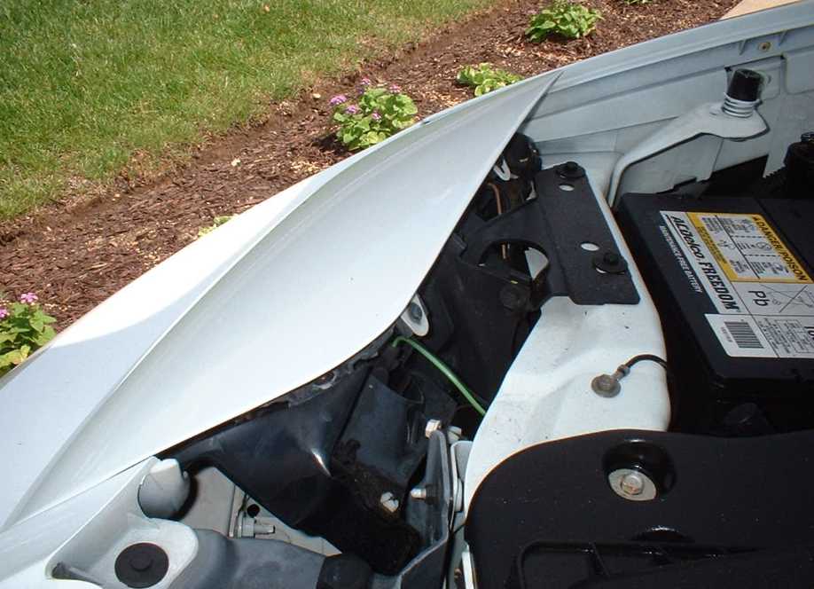
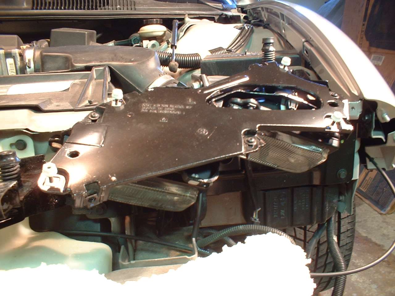
Phase One: Disassemble Stock
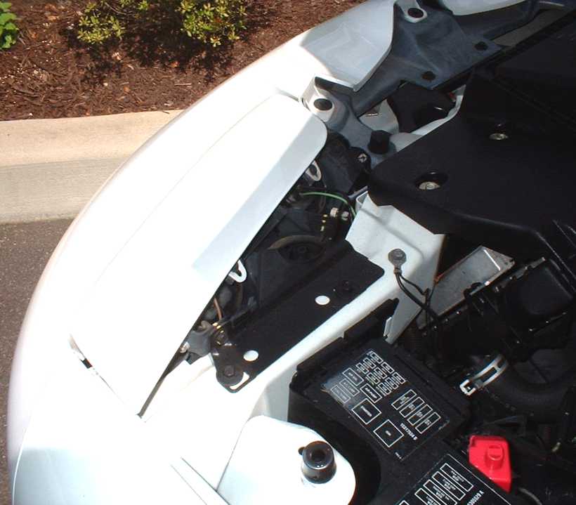
Front End Phase Two: Mounting New Head
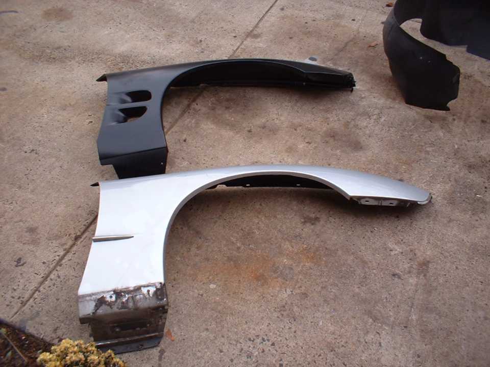
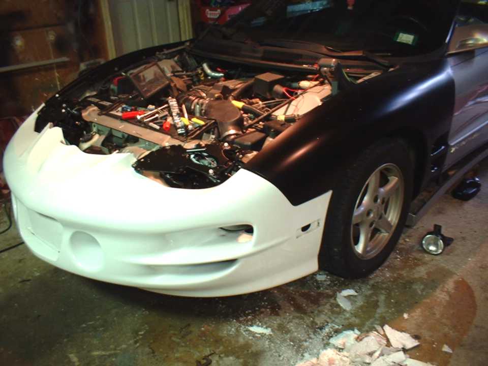
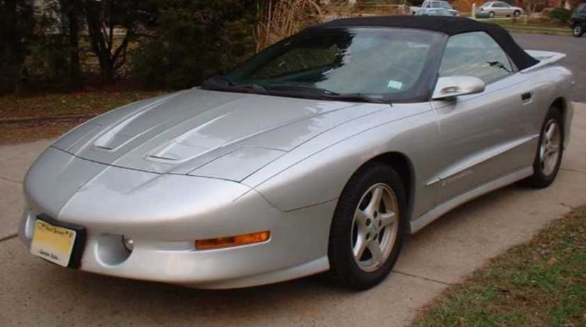
Lights The first two pictures show the stock 1995 head lights. The third picture is of the one piece headlight assembly removed from the car. The forth and fifth pictures are of how the new fully assembled headlights will look once installed. I acquired this picture from a local car dealership when I was doing my research for the project. The last picture is of the assembled drivers side headlight assembly. Phase Three: Mounting the Fenders Phase Four: Mounting the Front
Clip Phase Five: Repositioning the Fog
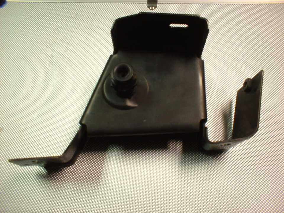
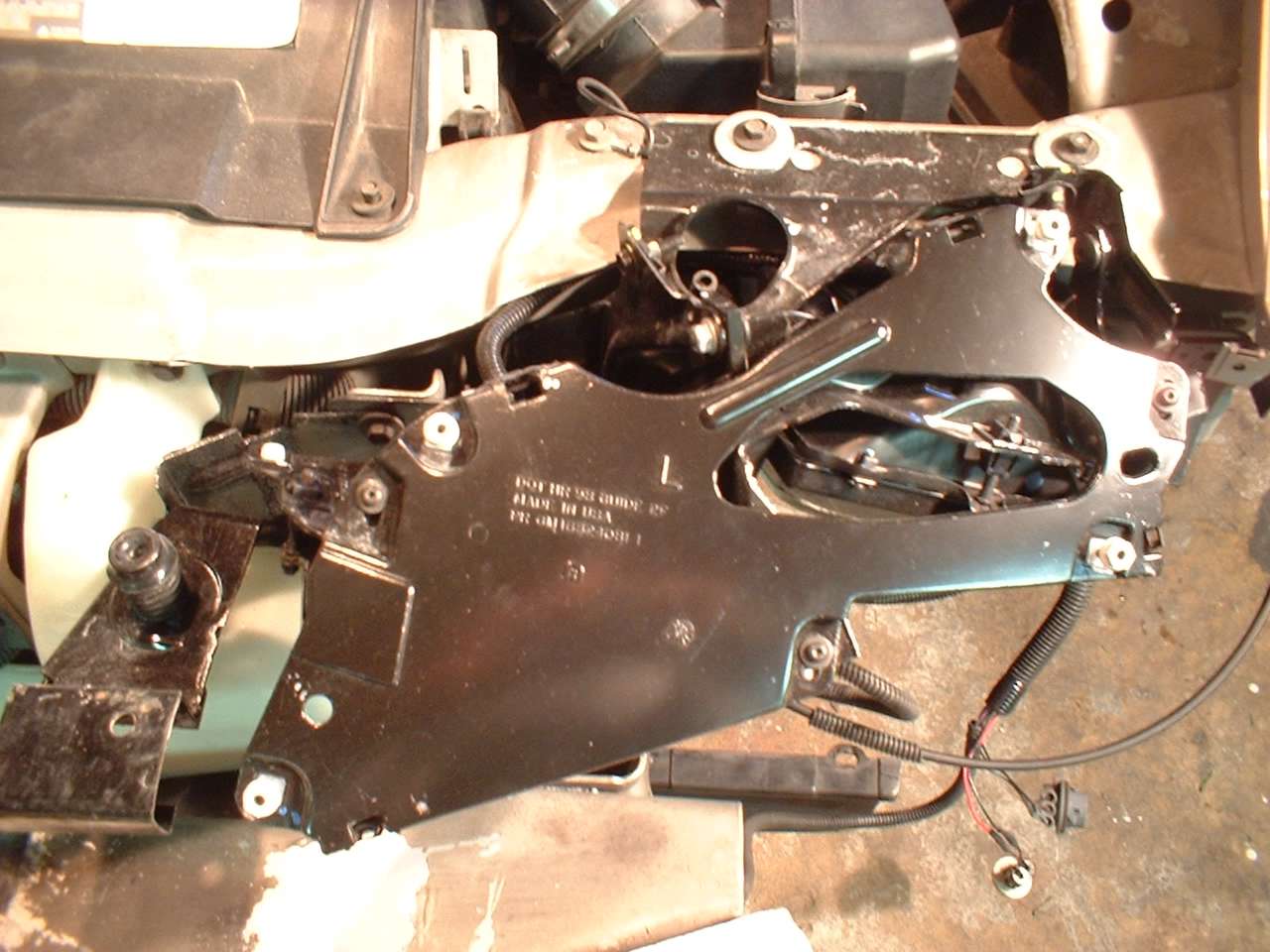
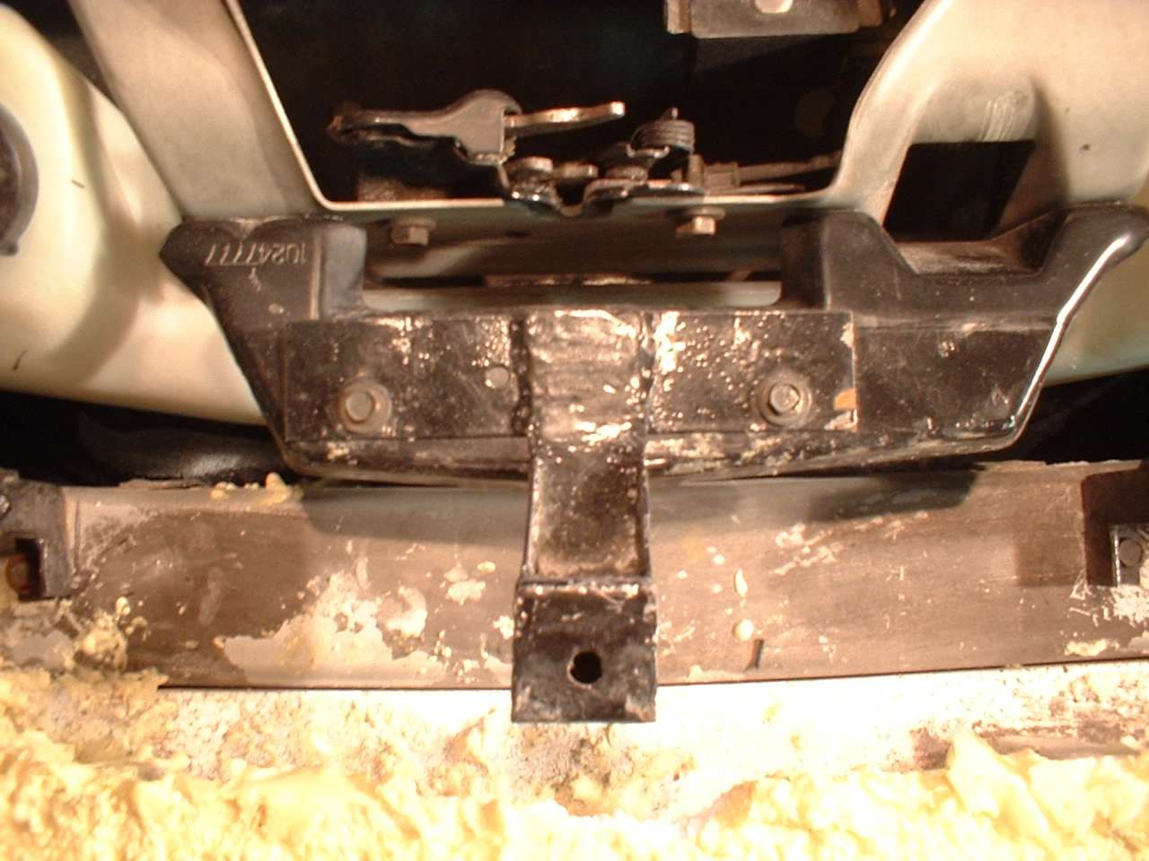
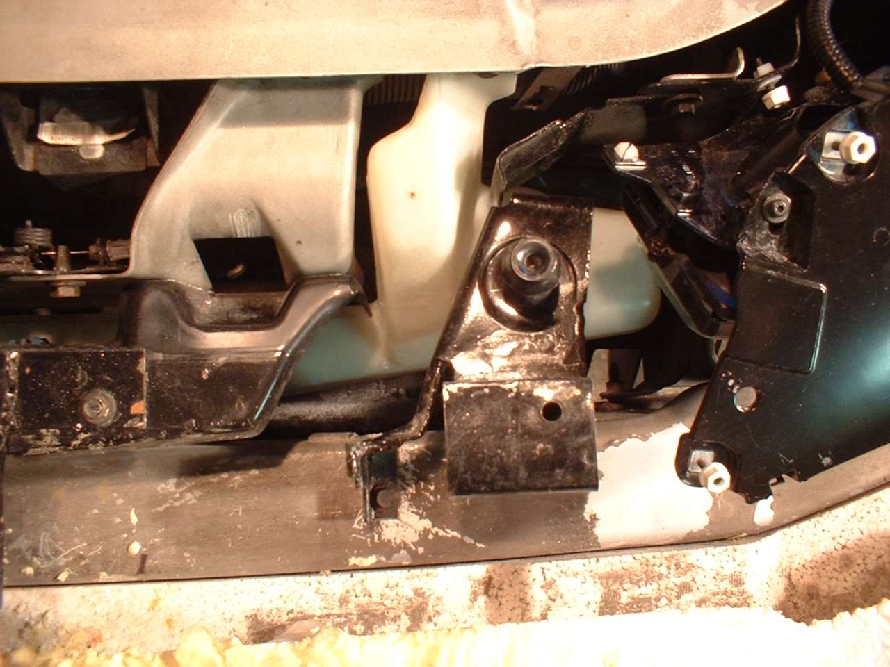
Lights Phase Six: Fabrication of Front
Clip Mounting Points Phase Seven: Mounting the Ram Air Hood
Phase Eight: Mounting the Inner Fenders and Miscellaneous
|
|
Send mail to
sales@dav-electronics.com with questions or comments about this web
site.
Camaro and Firebird are registered trademarks of General Motors Corporation.
|


.jpg)
.jpg)
.jpg)
.jpg)
.jpg)